

This chapter introduces you to the type of practical electronics that you need to work correctly and effectively in interfacing electronic circuits with the Raspberry Pi (RPi) platform. The chapter begins by describing some equipment that can be very helpful in developing and debugging electronic circuits. It continues with a practical introductory guide to circuit design and analysis, in which you are encouraged to build the circuits and utilize the equipment that is described at the beginning of the chapter. The chapter continues with a discussion on the typical discrete components that can be interfaced to the general-purpose input/outputs (GPIOs) on the RPi, including diodes, capacitors, transistors, optocouplers, switches, and logic gates. Finally, the important principles of analog-to-digital conversion (ADC) are described, as such knowledge is required in Chapter 9 to build circuits that interface the RPi to analog sensors.
After completing this chapter, you should hopefully be able to do the following:
- Describe the basic principles of electrical circuit operation, build circuits on breadboards, and measure voltage and current values.
- Use discrete components such as diodes, LEDs, transistors, and capacitors in your own circuit designs.
- Use transistors and FETs as switches to control higher current and voltage signals than would be possible by using the RPi outputs on their own.
- Interconnect and interface to logic gates, being particularly aware of the issues that arise with “floating” inputs.
- Describe the principles of analog-to-digital conversion and design basic operational-amplifier circuits.
- Combine all of these skills to build the type of circuits that are important for safely interfacing to the RPi GPIOs.
Contents
- 1 Parts for this Chapter
- 2 Digital Media Resources
- 2.1 Custom Cables with the Raspberry Pi
- 2.2 The Analog Discovery (Analog Discovery 2)
- 2.3 Debouncing a SPDT Slider Switch
- 2.4 Debouncing a SPST Push Button Switch
- 2.5 The Two’s Complement
- 2.6 Overflow, Overflow Detection and Underflow
- 2.7 Logic Gates – Integrated Circuits
- 2.8 The JK Flip-Flop
- 2.9 A 555-Timer Circuit
- 3 Some Images from the Chapter
- 4 External Resources
Parts for this Chapter
Here is a full list of the components that are used in this chapter:
■ Breadboard
■ Diodes: 1N4001, general‐purpose LED
■ Transistors: NPN: BC547, FET: BS270
■ Voltage regulator: KA7805/LM7805
■ PTC: 60R110
■ Button and Switch: General purpose SPST and SPDT
■ ICs: 74HC73N, 74HC03N, 74LS08N, 74HC08N, 74HC14, LM358N
■ Resistors: 1 MΩ, 2.2 kΩ, 2×10 kΩ, 50 kΩ, 100 Ω, 50Ω, 1 kΩ, 470Ω, 220 Ω, 100 kΩ POT.
■ Capacitors: 10μF, 1μF, 0.33μF, 0.1μF.
■ Opto‐isolator: SFH617A
Digital Media Resources
Here the digital resources referred to in the chapter web page are provided. There are high-resolution versions of some of the important figures and links to videos, resources and websites that are described in the chapter.
Custom Cables with the Raspberry Pi
Building custom cables using a DuPont PCB Connector and a crimping tool. Here are some example suppliers:
The Analog Discovery (Analog Discovery 2)
In this video I investigate the use of the Digilent Analog Discovery with Waveforms and look how it can be used for the analysis of analog and digital circuits. The Analog Discovery (and Analog Discovery 2) is a USB oscilloscope, waveform generator, digital pattern generator and logic analyzer. The Analog Disovery 2 is priced at $279. l demonstrate three different applications of the Discovery:
– Analog analysis of a rectifier diode.
– Using the digital pattern generator and logic analyzer to investigate the behavior of a JK flip-flop.
– Using the logic analyzer and its I2C interpreter to connect to the BeagleBone I2C bus and analyse how it behaves when we use the Linux i2c tools. This is exactly the same under the Raspberry Pi platform.
Debouncing a SPDT Slider Switch
This video discusses what is switch bouncing and explains how we can debounce a SPDT (single pole double throw) slide switch. It uses an SR latch to achieve debouncing and it shows how we can implement this circuit using 74LS00 NAND gates. It also examines the output of this circuit using an oscilloscope and demonstrates that the circuit is working effectively. This is part 1, in the next part I will explain how to debounce a SPST momentary push button switch using a RC circuit and a Schmitt trigger.
Debouncing a SPST Push Button Switch
This video explains how we can debounce a SPST (Single Pole Single Throw) momentary push button switch. It describes the concept of hysteresis and the use of a Schmitt Trigger. The circuit uses a RC low-pass filter as the input to a 74HCT14 Hex Schmitt Trigger to achieve debouncing and it shows how we can implement and test this circuit using an oscilloscope. This is part 2 – in the previous video I explained how to debounce a SPDT slide switch using a SR latch.
The Two’s Complement
The Two’s Complement is a method of representing negative/signed binary numbers that is commonplace in digital electronics and is the basis for how signed integers are represented in embedded systems. This tutorial explains the need for the Two’s Complement form and describes how you can perform operations such as additions/subtractions and multiplications using this form. It provides some numerical examples with solutions to allow you to test your understanding of the materials that are presented.
Overflow, Overflow Detection and Underflow
In this video I will look at the problems that can arise in unsigned and signed systems with overflow and underflow, which is where our system goes beyond its physical limitations. I will look at how you can detect that overflow is occurring in a digital system and how you can design a logic circuit to detect its occurrence. The video then describes underflow and finally, presents a few interesting questions with solutions.
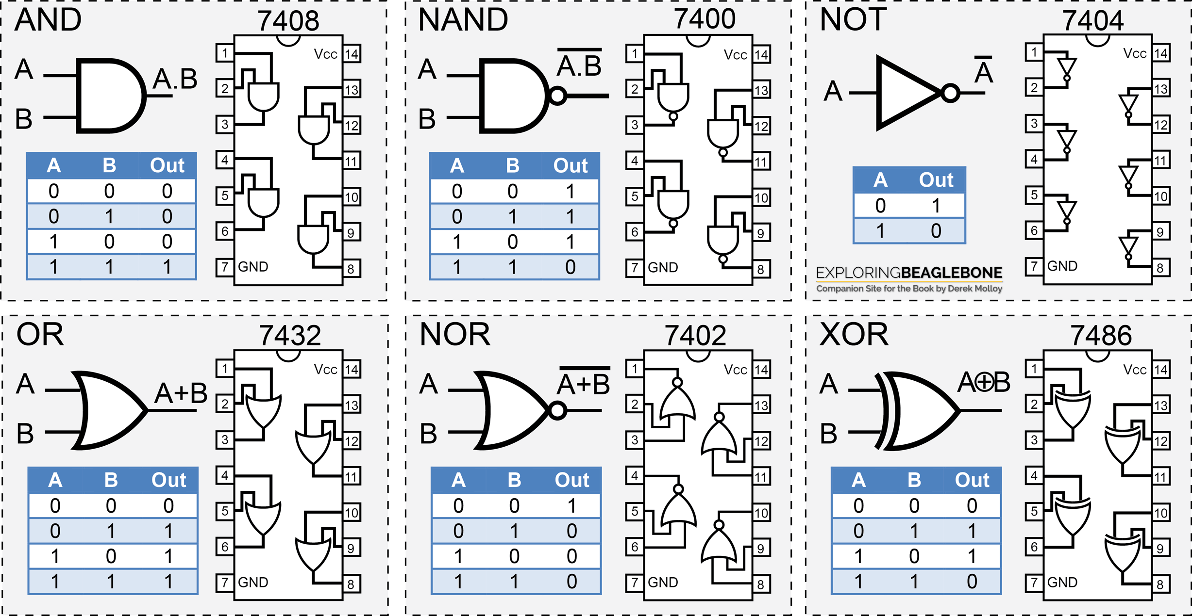
Logic Gates – Integrated Circuits
An introduction to simple logic gates using the 74HC08 quad two-input AND gates.
The JK Flip-Flop
This video lecture/tutorial describes the JK Flip-Flop in detail. I begin by describing the general operation of a 7473 JK flip-flop, showing the toggle state that makes this flip-flop important for many applications. Then I show in detail how we can create a JK flip-flop using NAND gates, describing both edge-triggered and pulse-triggered configurations. I implement both types of circuit, using a pulse generator for the edge-triggered version and a master-slave JK flip-flop for the pulse-triggered implementation. Finally, I show how we can add asynchronous set and reset inputs for the master-slave configuration and implement a circuit to demonstrate that this works correctly.
A 555-Timer Circuit
This is an experiment to set up a low frequency clock signal that we can use to drive our logic gate circuits. The clock will have a frequency of 1Hz, which will allow us to see the changes to our circuit as the clock cycles.
Some Images from the Chapter
External Resources
- T. R. Kuphaldt, “Lessons in Electric Circuits,” a free series of textbooks on the subjects of electricity and electronics: www.ibiblio.org/kuphaldt/electricCircuits/
- All About Circuits: www.allaboutcircuits.com provides excellent applied examples of many types of electronic circuits.
- The Electronics Club: www.electronicsclub.info
Errata
- Page 188. The formula on line 27 has stray parentheses and should read R = Vr/Ir = 5V
Recommended Books on the Content in this Chapter
The Ch. 4 Errata should apply to page 118, not pate 188.
The equation should read: R=Vr/Ir =5V/100ma= 50 ohms
For the component list. There are so much to choose from at Farnell/Elfa etc… It would be really nice to have listed the Farnell product numbers or similar, so we get exactly what we need.
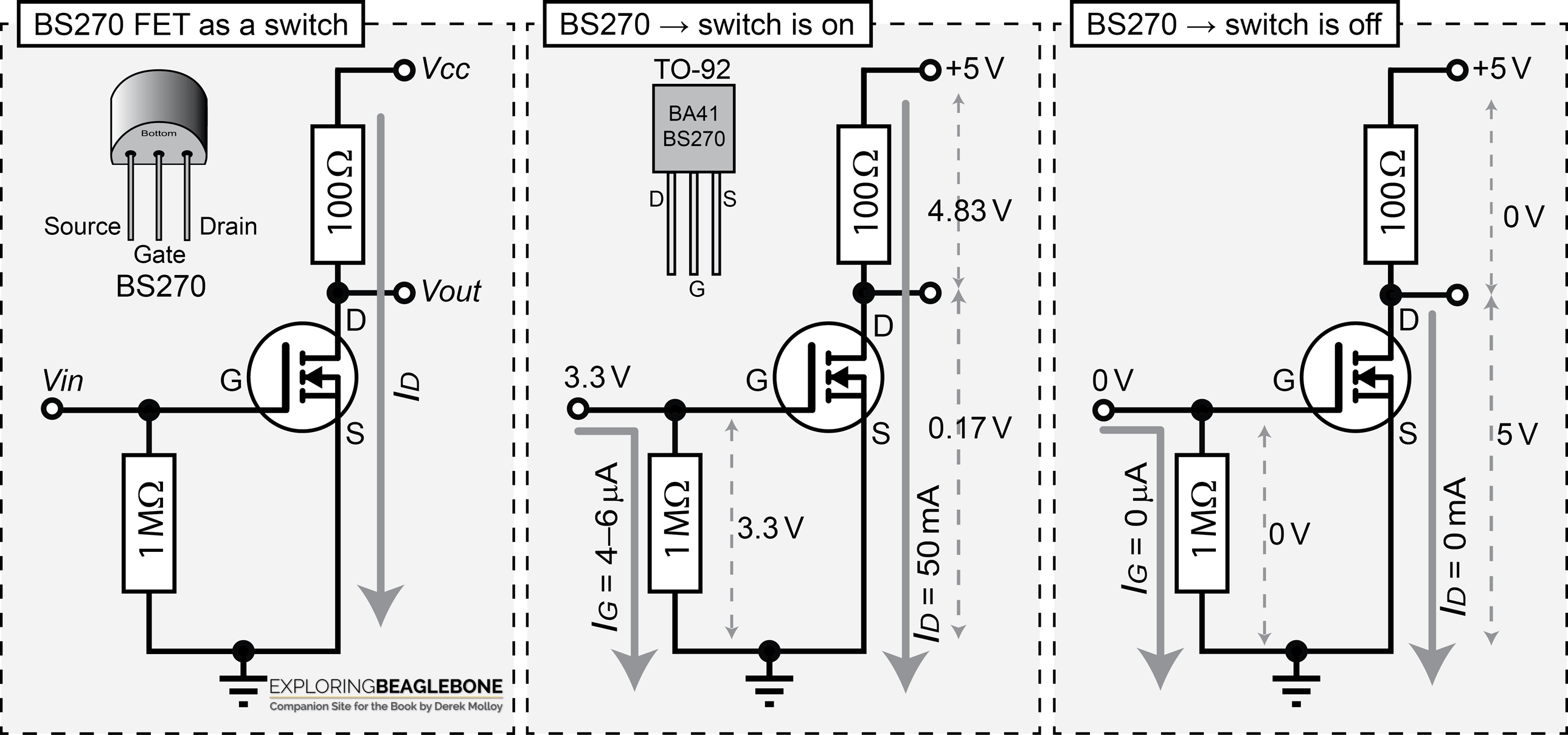
I tried to repeat the MOSFET experiment in this chapter, it damage the transistor when I fed in 1MHz pulse from analog discovery 2, so I refer to BS270 datasheet (http://www.farnell.com/datasheets/2264923.pdf?_ga=2.49991718.101956756.1502767186-603351120.1483770701), and found out the transistor if switched above 10KHz (while Vds = 5V) will draw over 2A and damage the transistor. Hope the author can help clarify this.
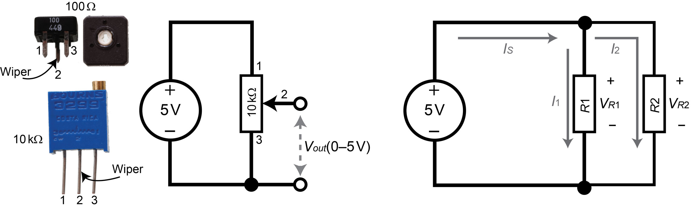
On page 121 the top equations for the current divider rule both I1 and I2 are equivalent as written. Shouldn’t I2 be equal to I x ( R1/(R1+R2) . Then the numbers come out in the above example. Also Is = I1 + I2 = 50mA + 25 mA = 75mA.
Yes, the correct equation for I2 would be I x (R1/(R1 +R2))
Prof.Molloy, I suppose the truth table for the flip-flop in the “Debouncing a SPDT” is wrong. Input S
=0 & R´=1 should output Q=1, and of course, for the Input of S=1 & R´=0 should result in the Q=0.