Introduction
This is the chapter web page to support the content in Chapter 10 of the book: Exploring Raspberry Pi – Interfacing to the Real World with Embedded Linux. The summary introduction to the chapter is as follows:
In this chapter, you learn how to build on your knowledge of general-purpose input/output (GPIO) and bus interfacing. In particular, you can combine hardware and software to provide the Raspberry Pi (RPi) with the ability to interact with its physical environment in the following three ways: First, by controlling actuators such as motors, the RPi can affect its environment, which is very important for applications such as robotics and home automation. Second, the RPi can gather information about its physical environment by communicating with sensors. Third, by interfacing to display modules, the RPi can present information. This chapter explains how each of these interactions can be performed. Physical interaction hardware and software provides you with the capability to build advanced projects (for example, to build a robotic platform that can sense and interact with its environment). The chapter finishes with a discussion on how you can create your own C/C++ code libraries and utilize them to build highly scalable projects.
After completing this chapter, you should hopefully be able to do the following:
- Interface to actuators, such as DC motors, stepper motors, and relays.
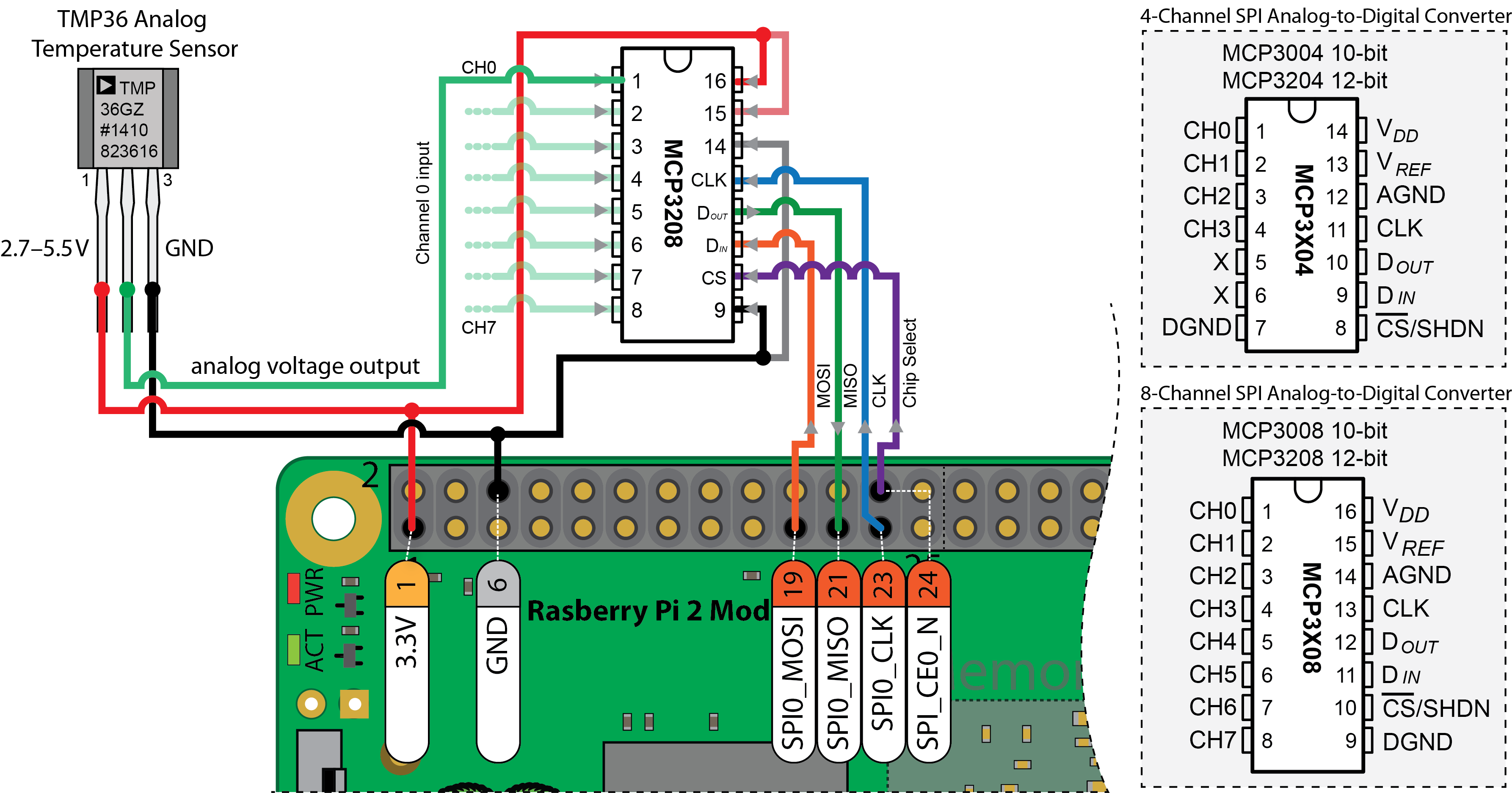
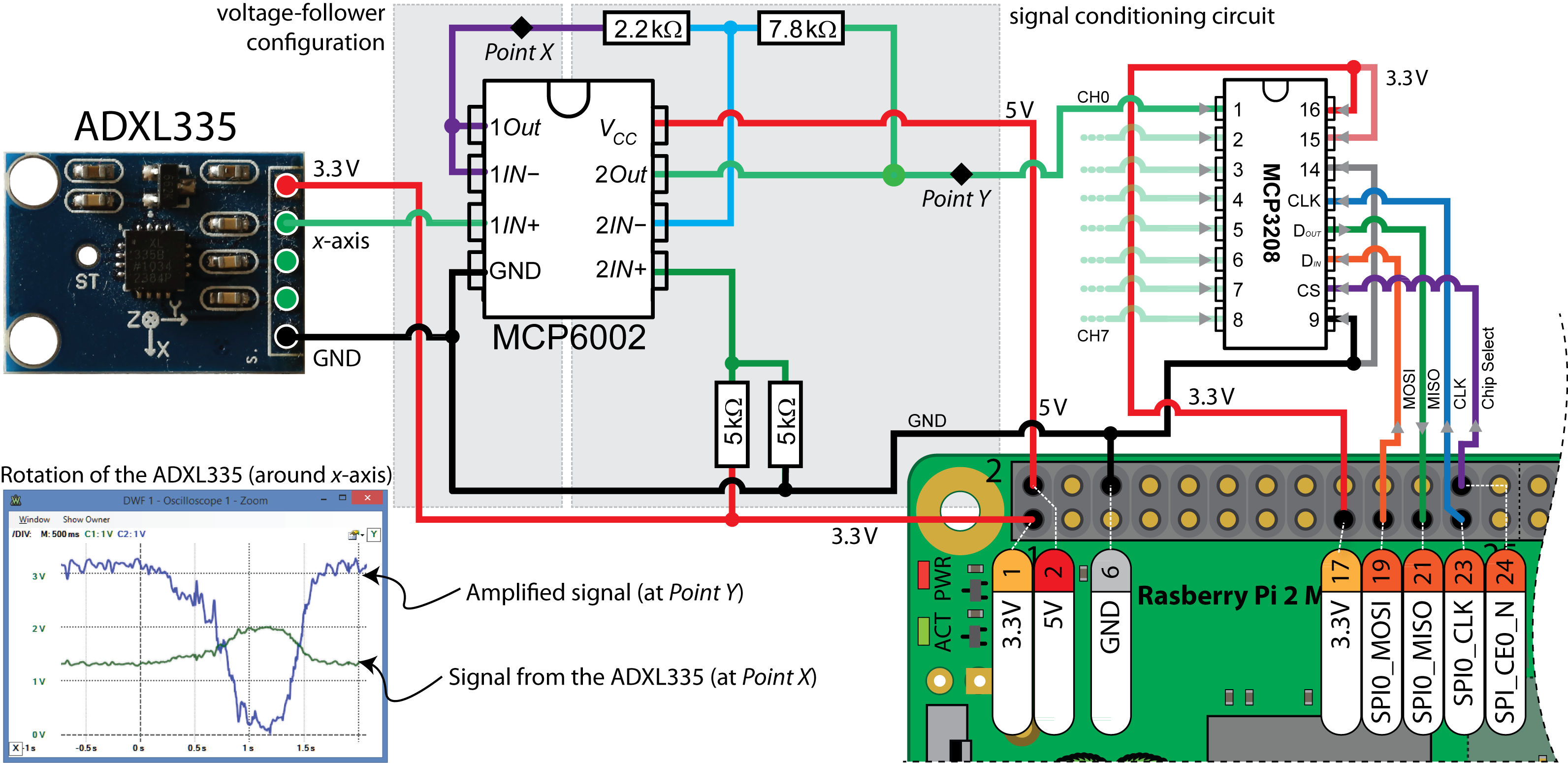
- Condition a sensor signal so that it can be interfaced to an SPI ADC, which is attached to the RPi.
- Correctly interface analog sensors such as distance sensors, temperature sensors, and accelerometers to the RPi.
- Interface to low-cost display modules such as seven-segment displays, character LCD displays, and OLED dot-matrix displays.
- Utilize makefiles and CMake to build libraries of code that can be used to build highly scalable C/C++ projects.
Driving Stepper Motors with the EasyDriver Board
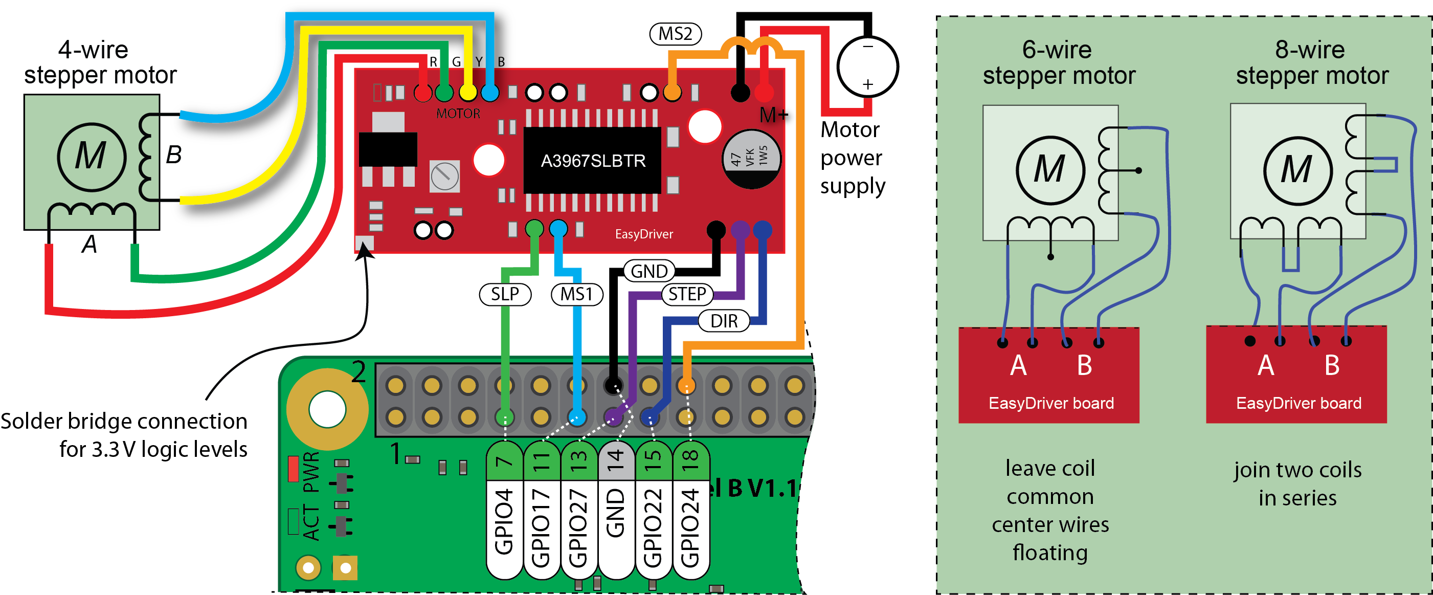
This video examines how we can drive stepper motors using C++ within Embedded Linux using the open source hardware EasyDriver board. The video begins by describing stepper motors and the effects of micro-stepping. It then discusses the EasyDriver Board (V4.4) and all of the available inputs and outputs. The board uses the Allegro A3967 which allows for full, half-, quarter and one eight micro-stepping. The video then describes C++ code that uses the GPIOs on an embedded Linux device to wrap the EasyDriver with a C++ class.
Source Code Examples
All of the source code that is described in this book is available in a public GitHub repository: Derek Molloy Exploring Raspberry Pi repository.
You can clone this repository on a Linux desktop computer or your Raspberry Pi using the command:
|
1 |
git clone https://github.com/derekmolloy/exploringrpi.git |
The code for this chapter can be accessed in the chp10 folder of the cloned repository. Some formatted code is provided here for your convenience.
|
1 2 3 4 5 6 7 8 9 10 11 12 13 14 15 16 17 18 19 20 21 22 23 24 25 26 27 28 29 30 31 32 33 34 35 36 37 38 39 40 41 42 43 44 45 46 47 48 49 50 51 52 53 54 55 56 57 58 59 60 |
/* * SPIDevice.h Created on: 22 May 2015 * Copyright (c) 2015 Derek Molloy (www.derekmolloy.ie) * Made available for the book "Exploring Raspberry Pi" */ #ifndef SPIDEVICE_H_ #define SPIDEVICE_H_ #include<string> #include<stdint.h> #include"BusDevice.h" #define SPI_PATH "/dev/spidev" namespace exploringRPi{ /** * @class SPIDevice * @brief Generic SPI Device class that can be used to connect to any type of SPI device and * read or write to its registers */ class SPIDevice:public BusDevice { public: /// The SPI Mode enum SPIMODE{ MODE0 = 0, //!< Low at idle, capture on rising clock edge MODE1 = 1, //!< Low at idle, capture on falling clock edge MODE2 = 2, //!< High at idle, capture on falling clock edge MODE3 = 3 //!< High at idle, capture on rising clock edge }; private: std::string filename; public: SPIDevice(unsigned int bus, unsigned int device); virtual int open(); virtual unsigned char readRegister(unsigned int registerAddress); virtual unsigned char* readRegisters(unsigned int number, unsigned int fromAddress=0); virtual int writeRegister(unsigned int registerAddress, unsigned char value); virtual void debugDumpRegisters(unsigned int number = 0xff); virtual int write(unsigned char value); virtual int write(unsigned char value[], int length); virtual int setSpeed(uint32_t speed); virtual int setMode(SPIDevice::SPIMODE mode); virtual int setBitsPerWord(uint8_t bits); virtual void close(); virtual ~SPIDevice(); virtual int transfer(unsigned char read[], unsigned char write[], int length); private: SPIMODE mode; uint8_t bits; uint32_t speed; uint16_t delay; }; } /* namespace exploringRPi */ #endif /* SPIDEVICE_H_ */ |
|
1 2 3 4 5 6 7 8 9 10 11 12 13 14 15 16 17 18 19 20 21 22 23 24 25 26 27 28 |
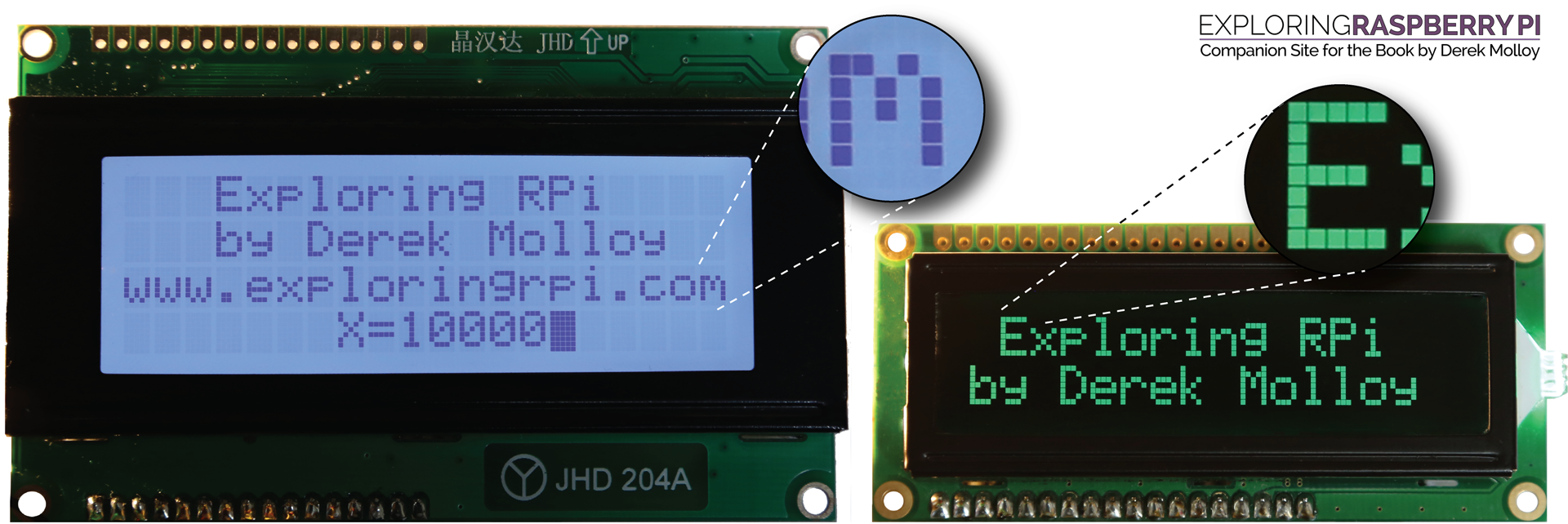
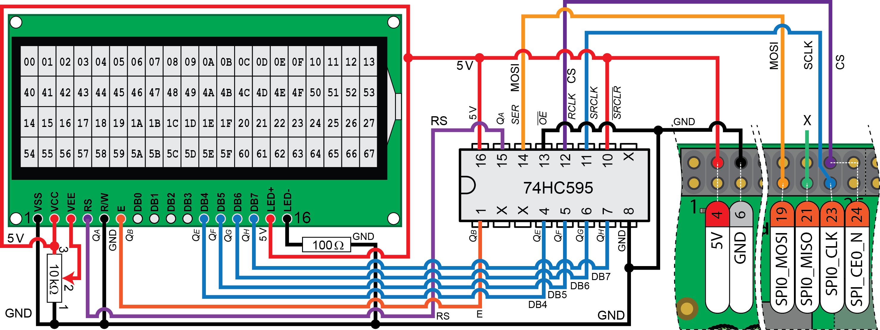
#include <iostream> #include <sstream> #include "display/LCDCharacterDisplay.h" using namespace std; using namespace exploringRPi; int main(){ cout << "Starting LCD Character Display Example" << endl; SPIDevice *busDevice = new SPIDevice(0,0); busDevice->setSpeed(1000000); // Have access to SPI Device object ostringstream s; // Using this to combine text and int data LCDCharacterDisplay display(busDevice, 20, 4); // Construct 20x4 LCD Display display.clear(); // Clear the character LCD module display.home(); // Move the cursor to the (0,0) position display.print(" Exploring RPi"); display.setCursorPosition(1,3); display.print("by Derek Molloy"); display.setCursorPosition(2,0); display.print("www.exploringrpi.com"); for(int x=0; x<=10000; x++){ // Do this 10,000 times s.str(""); // clear the ostringstream object s display.setCursorPosition(3,7); // move the cursor to second row s << "X=" << x; // construct a string that has an int value display.print(s.str()); // print the string X=*** on the LCD module } cout << "End of LCD Character Display Example" << endl; return 0; } |
|
1 2 3 4 5 6 7 8 9 10 11 12 13 14 15 16 17 18 19 20 21 22 23 24 25 26 27 28 29 30 31 32 33 34 35 36 37 38 39 40 41 42 43 44 45 46 47 48 49 50 51 52 53 54 55 56 57 58 59 60 61 62 63 64 65 66 67 68 69 70 71 72 73 74 75 76 77 78 79 80 81 82 83 84 85 86 87 88 89 90 91 92 93 94 95 96 97 98 99 100 101 102 103 104 105 106 107 108 109 110 111 112 113 114 115 116 |
#include<iostream> #include<unistd.h> #include<iomanip> #include "ArduiPi_OLED_lib.h" #include "ArduiPi_OLED.h" #include "Adafruit_GFX.h" #include <bcm2835.h> using namespace std; #define USING_DHT11 false // The DHT11 uses only 8 bits #define DHT_GPIO RPI_GPIO_P1_15 #define LH_THRESHOLD 22 // Low=~14, High=~38 - pick avg. int humid=0, temp=0; void waitDelay(int delay=100){ for (int i=0; i<delay; i++) {} // blocking delay } int getDHTReading(){ unsigned char data[5] = {0,0,0,0,0}; cout << "Getting a sample from the DHT Sensor\n"; bcm2835_gpio_fsel(DHT_GPIO, BCM2835_GPIO_FSEL_OUTP); bcm2835_gpio_write(DHT_GPIO, LOW); usleep(18000); // wait for 18ms bcm2835_gpio_write(DHT_GPIO, HIGH); bcm2835_gpio_fsel(DHT_GPIO, BCM2835_GPIO_FSEL_INPT); bcm2835_gpio_set_pud(DHT_GPIO, BCM2835_GPIO_PUD_DOWN); do { waitDelay(); } while(bcm2835_gpio_lev(DHT_GPIO)==HIGH); do { waitDelay(); } while(bcm2835_gpio_lev(DHT_GPIO)==LOW); do { waitDelay(); } while(bcm2835_gpio_lev(DHT_GPIO)==HIGH); // Remember the highs, ignore the lows -- a good philosophy! for(int d=0; d<5; d++) { // for each data byte // read 8 bits for(int i=0; i<8; i++) { // for each bit of data do { waitDelay(); } while(bcm2835_gpio_lev(DHT_GPIO)==LOW); int width = 0; // measure width of each high do { width++; waitDelay(); if(width>1000) break; // missed a pulse -- data invalid! } while(bcm2835_gpio_lev(DHT_GPIO)==HIGH); // time it! // shift in the data, msb first if width > the threshold data[d] = data[d] | ((width > LH_THRESHOLD) << (7-i)); } } if (USING_DHT11){ humid = data[0] * 10; // one byte - no fractional part temp = data[2] * 10; // multiplying to keep code concise } else { // for DHT22 (AM2302/AM2301) humid = (data[0]<<8 | data[1]); // shift MSBs 8 bits left and OR LSBs temp = (data[2]<<8 | data[3]); // same again for temperature } unsigned char chk = 0; // the checksum will overflow automatically for(int i=0; i<4; i++){ chk+= data[i]; } if(chk==data[4]){ cout << "The checksum is good" << endl; cout << "The temperature is " << (float)temp/10 << "°C" << endl; cout << "The humidity is " << (float)humid/10 << "%" << endl; } else { cout << "Checksum bad - data error - trying again!" << endl; usleep(2000000); // have to delay for 1-2 seconds between readings return -1; } return 0; } int main() { ArduiPi_OLED display; bool isTemperature = true; if (!bcm2835_init()){ cout << "Failed exiting " << endl; return 1; } if(!display.init(OLED_I2C_RESET, OLED_ADAFRUIT_I2C_128x64)){ perror("Failed to set up the display\n"); return -1; } printf("Setting up the I2C Display output\n"); display.begin(); display.setTextColor(WHITE); // keep updating the display until program is killed while(true){ display.setTextSize(1); display.clearDisplay(); display.setCursor(27,5); display.print("Exploring RPi"); while (getDHTReading() ==-1) {} // keep going until get a valid DHT reading printf("have reading\n"); if(isTemperature){ display.setCursor(30,18); display.print("Temperature:"); display.setCursor(20,37); display.setTextSize(3); display.printf("%02.1fC", (float)temp/10 ); } else { display.setCursor(40,18); display.print("Humidity:"); display.setCursor(20,37); display.setTextSize(3); display.printf("%02.1f%%", (float)humid/10 ); // space important } display.display(); printf("sleeping\n"); usleep(5000000); isTemperature=!isTemperature; } display.close(); bcm2835_close(); return 0; } |
|
1 2 3 4 5 6 7 8 9 10 11 12 13 14 15 16 17 18 19 20 21 22 23 24 25 26 27 |
/* Using the tmp36 sensor with the MCP3208 */ #include <iostream> #include "bus/SPIDevice.h" using namespace exploringRPi; using namespace std; float getTemperature(int adc_value){ // from the TMP36 datasheet float cur_voltage = adc_value * (3.30f/4096.0f); // Vcc = 3.3V, 12-bit float diff_degreesC = (cur_voltage-0.75f)/0.01f; return (25.0f + diff_degreesC); } int main(){ cout << "Starting the RPi TMP36 example" << endl; SPIDevice *busDevice = new SPIDevice(0,0); busDevice->setSpeed(1000000); // max frequency limit at 3.3V busDevice->setMode(SPIDevice::MODE0); unsigned char send[3], receive[3]; send[0] = 0b00000110; // Reading single-ended input from channel 0 send[1] = 0b00000000; // Use 0b00000001 and 0b10000000 for MCP3008 busDevice->transfer(send, receive, 3); float temp = getTemperature(((receive[1]&0b00001111)<<8)|receive[2]); float fahr = 32 + ((temp * 9)/5); // convert deg. C to deg. F cout << "Temperature is " << temp << " °C (" << fahr << "°F)" << endl; busDevice->close(); return 0; } |
Errata
None for the moment


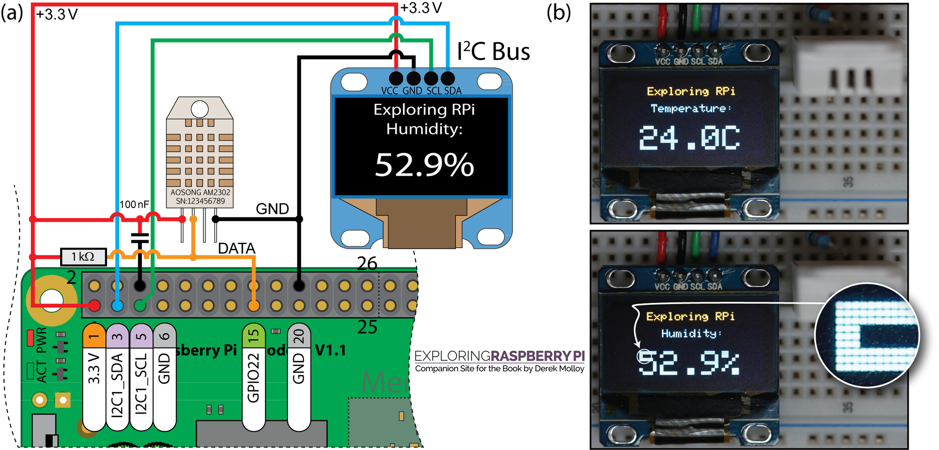
In Chapter 10, I am trying to run chp10/oled/dht (sudo ./dht) which compiles from oledDHT.cpp using the Aosong AM2301 but I am getting all checksum errors (each byte = 255). However, when I run the dht program from chp06 without any wiring changes, it works without problems. I removed the display but still I get the same error. I get no compile errors. Any ideas???
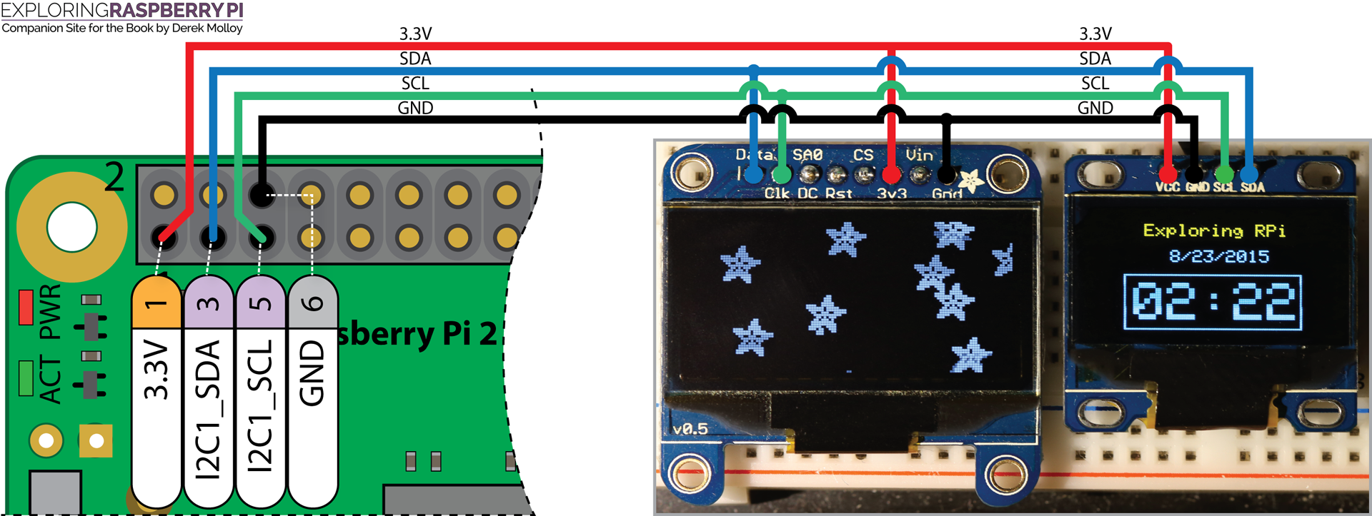
Note that the wiring diagram for the Adafruit 1.3″ OLED part is incorrect! The 3.3V power line from the Pi should be connected to the Vin line on the display, not the “3v3” line as shown here and in the book. (The Adafruit part has an on-board voltage regulator which generates 3.3V from the Vin supply, and the module’s “3v3” line is actually the regulated 3.3V *output*!)
@Craig: You might try playing with the “LH_THRESHOLD” constant in oledDHT.cpp. I was also getting checksum errors until I set that value to the high end of the range (38 in my case, running on a Pi 3 — this value seemed to work pretty good regardless of the CPU governor setting).